| Build Thread, Page :
1 2 3 4 5 [ 6 ] (114 posts, 20 posts per page, 6 pages in total)
|
[ < Prev ] |
| edtherenderman, Image # 43118 | 11 Apr 21 20:41 |

Side view of fuse after build and infill. Need to fill with spackling compound next. Note that the upper engine cowling has been removed. I plan to 3D print that, along with the cockpit combing. Also note that I added a lot of bracing between the formers. I’ve found in the past that when applying the tissue and shrinking it, the stringers on the edges will pull in and give a rippled effect. |
| edtherenderman, Image # 43117 | 11 Apr 21 20:37 |

Started work on the Rumpler kit this weekend. I had forgotten the quality of these kits. I think someone said, “Die Crushed” a couple of weeks ago, and that is what I found. Even a kit from the late 60’s still had pretty bad die cutting! I spent a lot of time rebuilding the fuse formers after pieces between stringers broke off while trying to cut them free of the sheet! But time spent here to get them right saves a lot of time when coverings. And besides, it’s not a race! |
| bsadonkill, Comment for image # 43111 | 06 Apr 21 11:33 |
| Yes, very impressive, and neat. |
| bsadonkill, Comment for image # 43109 | 06 Apr 21 11:27 |
| They were large displacement engines, around 900 cubic inch. They made around 200 HP at about 1600 RPM. That means they would have to produce more than 600 lb-ft of work! I think the DIVa was one of the first to use aluminum pistons in a Mercedes engine. This allowed them to up the compression ratio . |
| Don C, Comment for image # 43111 | 06 Apr 21 10:02 |
| I'm with Bob. It's quite impressive.
|
| jgood, Comment for image # 43109 | 05 Apr 21 15:24 |
| Yeah, I'm sure that was a ton of power back then. Cars of the day had, what, 20HP?! |
| edtherenderman, Comment for image # 43111 | 05 Apr 21 14:35 |
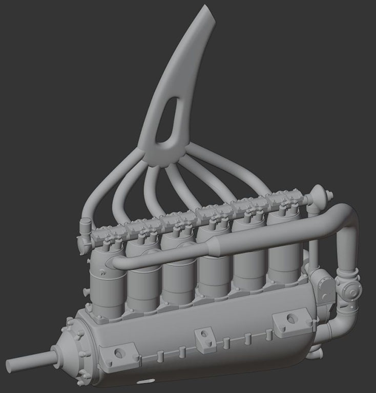
| Don't feel bad! I've got lots and lots of practice! I've been working in 3D since the early 90's so it comes somewhat naturally to me now. Doing these models, and printing them for the kits is a great deal of the enjoyment for me. It's another modeling media, like balsa and tissue. |
| edtherenderman, Comment for image # 43109 | 05 Apr 21 14:31 |
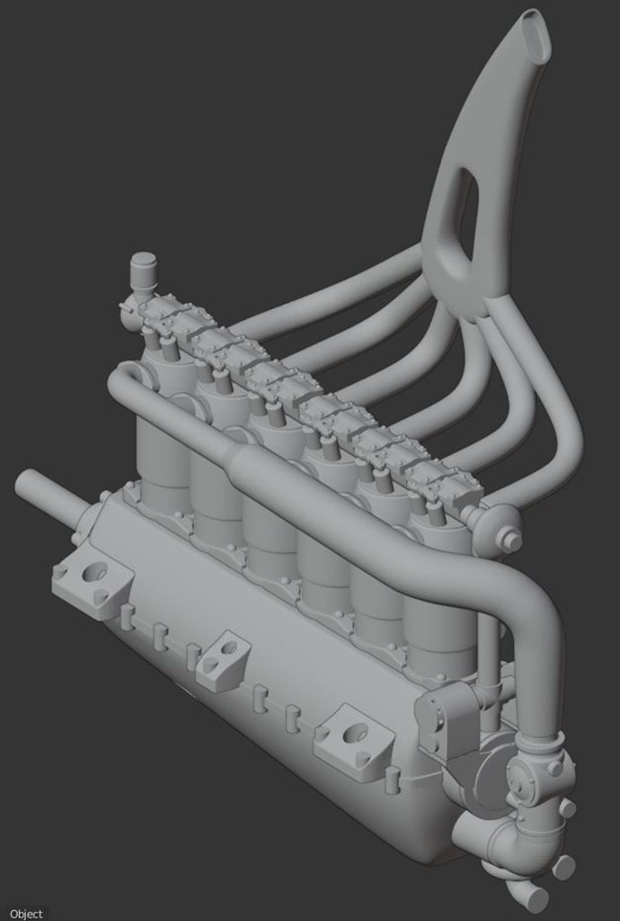
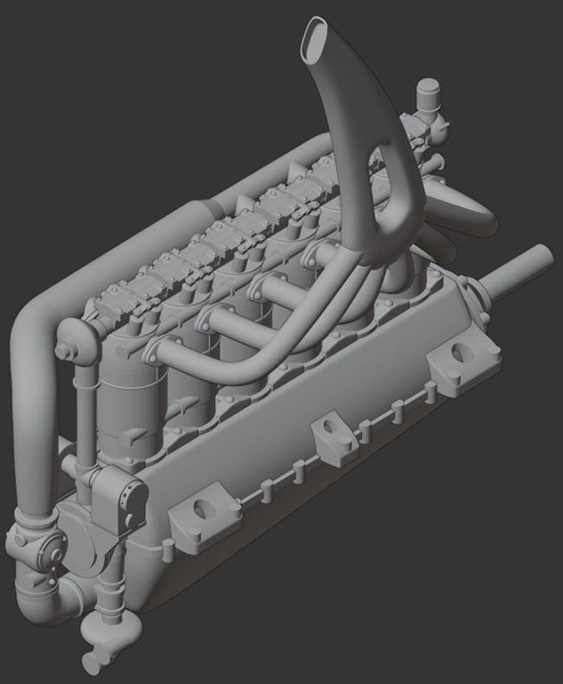
| I agree that this was a pretty advanced engine. The overhead cam was shaft driven from the crank. The same shaft drove the magnetos. I think they managed the fuel/air mixture with the decreasing diameter intake. Some model references I looked at (www.wingnutwings.com) show the manifold wrapped in cloth strips. Not sure to keep it cold or hot. Remembering that optimizing internal combustion engine performance in 1917 was a pretty new art, it's amazing they got ~120hp out of this engine. |
| bobgood, Comment for image # 43111 | 05 Apr 21 14:01 |
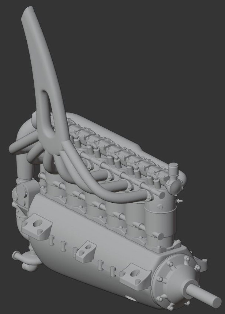
| These 3D model parts are amazing - I'm sad to say that I have no idea how you get those details into software, then get it to be 3D built. I'm a computer "duffer", sorry to admit! |
| jgood, Comment for image # 43109 | 05 Apr 21 13:43 |
| What an interesting, and advanced, engine for the time. Overhead cam, 4 valves per cylinder! That intake is interesting too - with the carb at the back, how did they get equal fuel/air into each cylinder? |
| edtherenderman, Image # 43112 | 04 Apr 21 18:14 |

|
| edtherenderman, Image # 43111 | 04 Apr 21 18:13 |

|
| edtherenderman, Image # 43110 | 04 Apr 21 18:13 |

|
| edtherenderman, Image # 43109 | 04 Apr 21 18:13 |

Starting work on the Guillows 200 series Rumpler C.5. 3D modeling the Daimler-Mercedes DIVa engine. The plan is to 3D print at the correct scale for this model. |
| Build Thread, Page :
1 2 3 4 5 [ 6 ] (114 posts, 20 posts per page, 6 pages in total)
|
[ < Prev ] |

