| Build Thread, Page :
1 [ 2 ] 3 (50 posts, 20 posts per page, 3 pages in total)
|
[ < Prev ] [ Next > ] |
| Creosotewind, Comment for image # 31614 | 15 May 14 11:47 |
| Congrats and enjoy all he brings you and your wife. Maybe someday he'll sit beside you on the workbench, building another P-38.
|
| David Duckett, Comment for image # 31614 | 15 May 14 11:38 |
| Congratulations! |
| SteveM, Image # 31614 | 15 May 14 11:06 |

This fella here is what derailed my P-38 build project. He was a little too eager to join me and had to spend 5 weeks in the NICU. Didn't help that I spent a lot of time building this crib instead of the P-38. Pardon the photo quality, my dear wife would rather use a $400 phone than an $800 camera. |
| BillParker, Comment for image # 30347 | 01 Jan 14 21:11 |
| oh! Yeah, that's it... *G* |
| SteveM, Comment for image # 30347 | 30 Dec 13 20:36 |
| Nah, you're just holding your computer upside down. |
| BillParker, Comment for image # 30347 | 30 Dec 13 12:33 |
| Uh Oh! You built one of your rudders upsidedown? *LOL* |
| SteveM, Comment for image # 30345 | 26 Dec 13 20:29 |
| After you get to this point it's a good idea to sand both sides of the front half to ensure the edges of the 1/16"x1/4" stock are flush so that the 1/16" square stock added later will sit flat. |
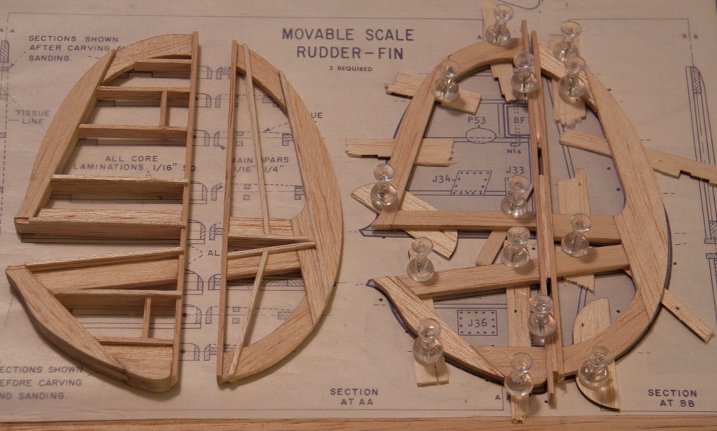
| SteveM, Image # 30347 | 26 Dec 13 20:27 |
Rudder-fin assembles ready for shaping. |
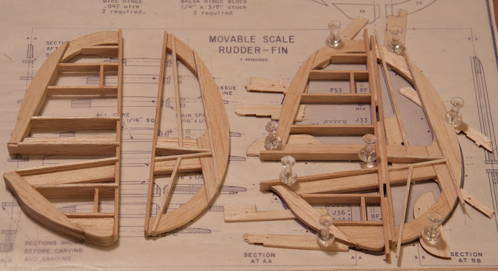
| SteveM, Image # 30346 | 26 Dec 13 20:26 |
In step 5 add the 1/16" square stock to the other side of the rear half. The front half gets C1A, C6A, and C7A added to both sides as well as 1/16" square stock to both sides of the four ribs nearest the fuselage. |
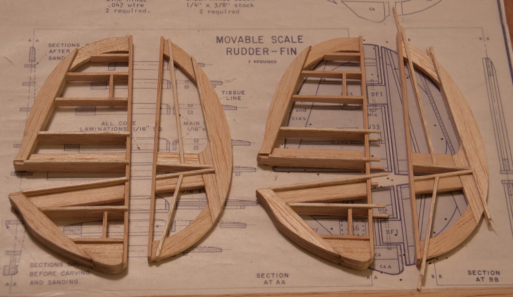
| SteveM, Image # 30345 | 26 Dec 13 20:24 |
In step 4 add all of the 1/16"x1/4" rib cores to the front half and 1/16" square pieces to the rear half. Note that the 1/16"x1/4" pieces run right across some openings where it doesn't belong, cut those out later after the parts are shaped. |
| SteveM, Image # 30344 | 26 Dec 13 20:20 |
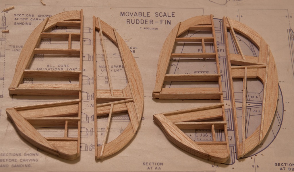
Here is a comparison of my "step 3" to a completed rudder-fin |
| SteveM, Image # 30343 | 26 Dec 13 20:19 |
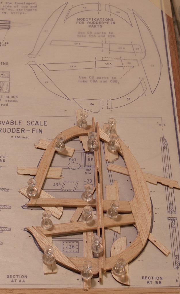
The instructions for building the elevator-stabilizer are fairly good, but for the rudder-fins simply say "build in a similar manner" which isn't particularly helpful so I will try to elaborate a bit. What you see here is step 3, the first step is to trim your sheet wood parts to fit the templates shown at the top of this photo. Step 2 is to join C1-C2-C9B, C6-C7-C8B, and C3-C4-C5-C8A-C9A together flat on the plans. Here in step 3 you raise those sheet wood assemblies up 1/16" using shims and glue on the vertical 1/16"x1/4" main spars with a 1/16" shim in the gap for the hinge. |
| SteveM, Image # 30337 | 24 Dec 13 15:58 |
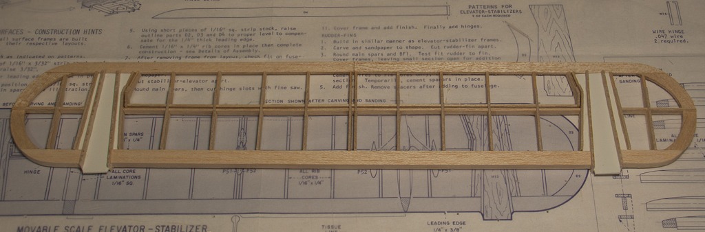
The movable scale elevator-stabilizer is built and ready for shaping. Progress has slowed lately for family gatherings such as my grandparent's 70th wedding anniversary. |
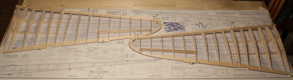
| SteveM, Image # 30252 | 14 Dec 13 15:56 |
The stringers are now on the wings. I think I'll wait to sand to shape and join the halves till after I've constructed the "action plan" details. |
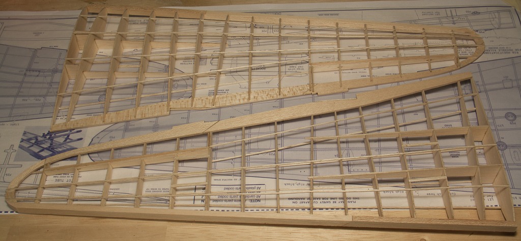
| SteveM, Image # 30249 | 12 Dec 13 00:39 |
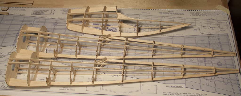
The wings are ready for stringers. |
| SteveM, Image # 30238 | 08 Dec 13 21:57 |
I decided to go ahead and add the stringers and the parts to support the wing before moving on to the wing construction. I really enoy putting stringers on laser cut models because of how accurately cut the notches are. |
| SteveM, Image # 30229 | 07 Dec 13 14:40 |
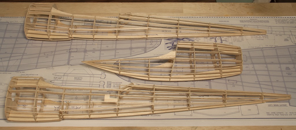
The nacelle and two fuselages are as far along as I can get them before adding the stringers. I'm torn between building the LG before adding the stringers and adding the stringers now and trying not to break them while adding the LG later. |
| poppy, Comment for image # 30216 | 03 Dec 13 16:44 |
| Hmmm, I've never found a problem with the edges. |
| SteveM, Comment for image # 30216 | 03 Dec 13 12:55 |
| I mainly sand it off because it looks unsightly to me and it would show through tissue covered models. In my little world a true craftsman takes time to tend to the little details. Another reason is that the diffusion of the laser creates an angled cut so the edge may need trued up for some joints to mate well.
I don't have any proof that the soot left behind interferes with a glue bond, it just makes sense to me that it would prevent a tight wood on wood joint. I could easily glue up some test examples, but the results would be very unscientific and subjective. |
| BriandKilby, Comment for image # 30216 | 03 Dec 13 11:25 |
| how come you have to sand the burn marks? does the glue not adhese? |
| Build Thread, Page :
1 [ 2 ] 3 (50 posts, 20 posts per page, 3 pages in total)
|
[ < Prev ] [ Next > ] |
