| Hangar |
Aircraft |
Category |
Date |
Preview |
| Skyediamonds1985 | Guillows Series 800 - Stearman PT-17 | Build | 03-Jul-15 21:32 | 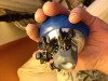 | | Views : 731 | | Each cylinder was first set in its "mounting base" made from paper and beads and then the whole assembly epoxied onto the plastic crankcase |
| Skyediamonds1985 | Guillows Series 800 - Stearman PT-17 | Build | 03-Jul-15 21:29 | 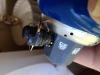 | | Views : 671 | | After each cylinder was epoxied in place, I cut a small section of slightly thick copper wiring and bent it to shape to simulate the exhaust. It was epoxied into place. The spark plug wiring was simply superglued. I purposely left the copper wiring in its natural state as sometimes exhaust pipes can take on various burnt hues of colors that closely resembles well, copper. |
| Skyediamonds1985 | Guillows Series 800 - Stearman PT-17 | Build | 03-Jul-15 21:24 | 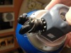 | | Views : 726 | | The plastic housing making up the nose of the fuselage and crankcase was painted in blue, silver for the exhaust collector ring, and gray for the crankcase. The cylinder was epoxied using the 5-minute brand. Again, why wait for 30 minutes while holding it in your hand for it to set? |
| Skyediamonds1985 | Guillows Series 800 - Stearman PT-17 | Build | 03-Jul-15 21:21 | 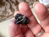 | | Views : 670 | | I used a T pin to make a hole in between the "cooling fins" for the spark plug and wiring. Then carefully pre-bent it back around the cylinder to its approximate location prior to gluing onto the crankcase. |
| Skyediamonds1985 | Guillows Series 800 - Stearman PT-17 | Build | 03-Jul-15 21:17 | 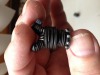 | | Views : 615 | | What can I say? |
| Skyediamonds1985 | Guillows Series 800 - Stearman PT-17 | Build | 03-Jul-15 21:16 | 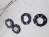 | | Views : 608 | | For the mounting base of each cylinder, i simply cut circular rings from paper (I figured it was far easier than cutting plastic with an X-Acto knife) and used small beads to simulate the mounting lugs. If you look carefully, you can easily see that I used a small diameter copper tubing with the same sized beads for simulating spark plugs. I left the beads in their natural bright metallic finish for that added "bling" factor. |
|
| Hangar |
Aircraft |
Category |
Date |
Preview |
| Skyediamonds1985 | Guillows Series 800 - Stearman PT-17 | Build | 03-Jul-15 21:09 | 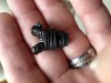 | | Views : 586 | | Just a dash of flat black spray but not too much. Want to allow that silver from the rings to show through for that metallic look. It was at this point I fabricated extra cooling fins for the exhaust side by cutting small sections of extra rings over a small piece of balsa. Then painted a flat gray as seen on the real engine. Besides, it kind of highlights the added detailing anyway. |
| Skyediamonds1985 | Guillows Series 800 - Stearman PT-17 | Build | 03-Jul-15 21:04 | 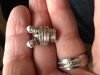 | | Views : 654 | | Ahem...again. Note the cylinder is starting to take shape. It only took a dash of Spackling compound on top of each end to simulate the valve covers. Again, a quick build without the added hassles of vacuum forming (of which I don't have anyway). I simply cut some extra rings in half and glued them in between the "V." |
| Skyediamonds1985 | Guillows Series 800 - Stearman PT-17 | Build | 03-Jul-15 20:56 |  | | Views : 565 | | Cylinder is starting to take shape |
| Skyediamonds1985 | Guillows Series 800 - Stearman PT-17 | Build | 03-Jul-15 20:52 | 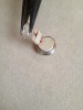 | | Views : 567 | | This photo is only for illustrated purposes as the elongated ring would have been slipped over the balsa support before gluing onto the top of the upper cylinder half. |
| Skyediamonds1985 | Guillows Series 800 - Stearman PT-17 | Build | 03-Jul-15 20:49 | 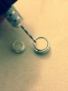 | | Views : 498 | | This may seem a bit out of sequence, but just using a pin vise over a previously set hole from the use of a T pin, at an apprx. angle to the "V" for the extra cooling fins and support. |
| Skyediamonds1985 | Guillows Series 800 - Stearman PT-17 | Build | 03-Jul-15 20:46 | 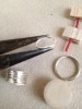 | | Views : 477 | | Let's try this again. I'm still learning to post, so sorry about that guys. I should point out that I purposely kept the upper and lower halves of the cylinders apart as I found out (the hard way, of course) that when slipping down the tightly squeezed rings, I kept breaking them apart. So each half had its respective sized rings slipped on. To make the "V: portion, I simply squeezed the rings to form an elongated "O" to suit the size of the two balsa strips used as formers. Again, a bit of fussing around, but still better than the alternate methods. |
|
