| Build Thread, Page :
1 2 [ 3 ] 4 (70 posts, 20 posts per page, 4 pages in total)
|
[ < Prev ] [ Next > ] |
| Skyediamonds1985, Image # 34299 | 30 Jun 15 19:34 |
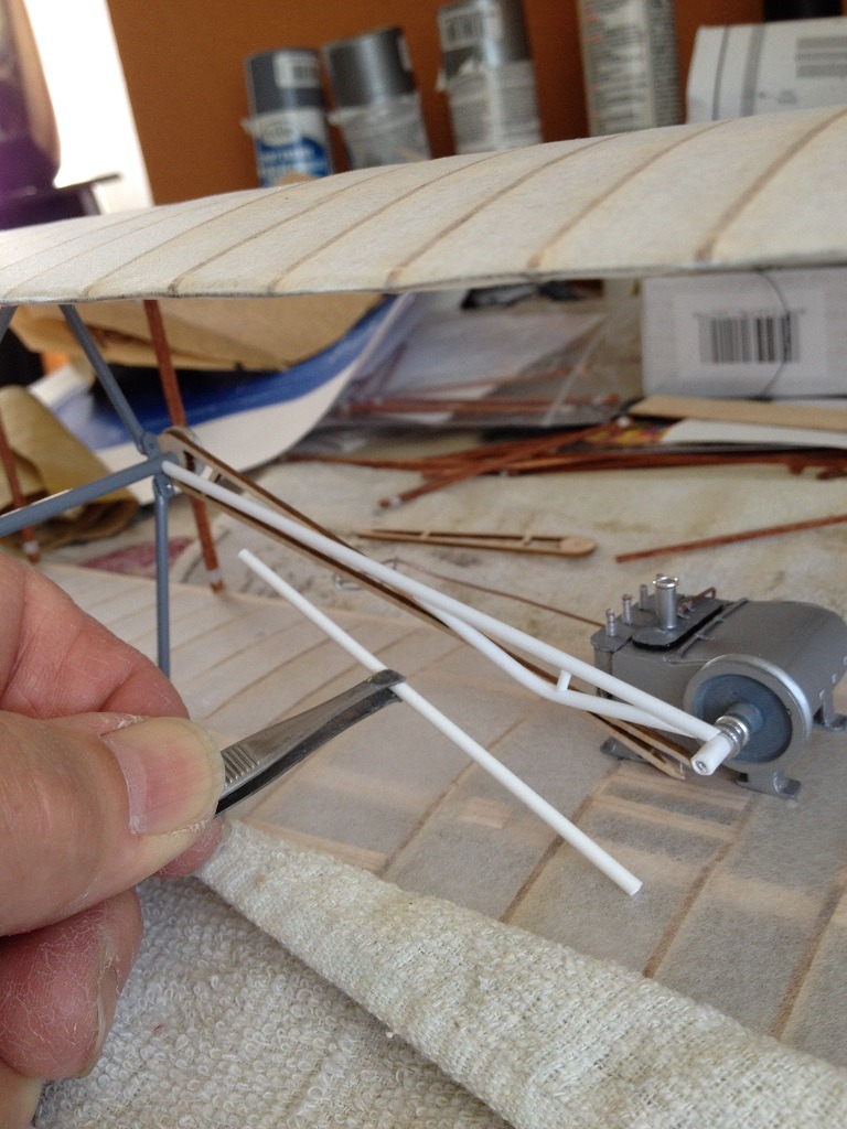
Assembling the tubular drive from the engine to the prop mounts. If you look carefully, you can see the original wooden Guillow 's drive b |
| Skyediamonds1985, Image # 34298 | 30 Jun 15 19:30 |

Assembling the top and bottom wings together and using the cut outs from the kit box as a jig. The prop mounts are included. |
| Skyediamonds1985, Image # 34292 | 29 Jun 15 12:28 |
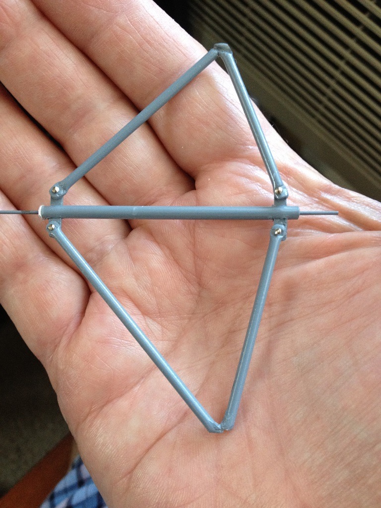
After fabricating the engine, the next step with to construct the propeller mounts. I deviated from the plans calling for balsa wood and decided to use thin styrene plastic tubing. |
| Skyediamonds1985, Image # 34281 | 26 Jun 15 23:05 |

Pilot's cradle and foot rest. I think I've burned my eyes enough for tonight. Hope you guys will enjoy. Sky |
| Skyediamonds1985, Image # 34280 | 26 Jun 15 23:03 |

For the pilot's cradle, I cut up some small dia. wire to brace along the semi-vertical wood stained balsa strips. |
| Skyediamonds1985, Image # 34279 | 26 Jun 15 22:59 |
End result. Used small copper writing to simulate fuel line, ultra thin strips of scotch tape as metal hold-down tabs over the oil and fuel lines leaving enough to route through the plane to the fuel tank. |
| Skyediamonds1985, Image # 34278 | 26 Jun 15 22:55 |

For the carburetor I used a soda straw and a small ring from (again) an arts & crafts store. The small ring serves as a "lip" to the top of the carburetor. |
| Skyediamonds1985, Image # 34277 | 26 Jun 15 22:53 |

Using the small chains purchased at the arts & crafts store, glued the appropriate sized gears to small copper wiring used as a drive shaft |
| Skyediamonds1985, Image # 34276 | 26 Jun 15 22:50 |

While at the local hobby store, also purchased various sized plastic gears |
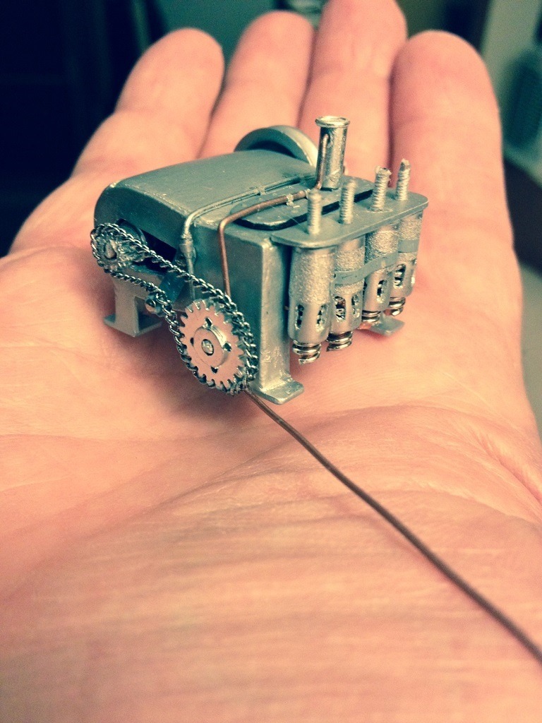
| Skyediamonds1985, Image # 34275 | 26 Jun 15 22:47 |

Just prior to gluing the cylinders I wrapped each with a thin slice of silkspan to give them a textured look. Also took a small 10mm (I think) dia, wire for the oil line. And used a couple of small slices of tape for the connection at the oil line as shown on the real engine. |
| Skyediamonds1985, Image # 34274 | 26 Jun 15 22:43 |

Sorry about the confusion on classifying the aircraft. Still new at this posting. I purchased small springs from arts and crafts store and cut small sections of copper wire for each cylinder. |
| Skyediamonds1985, Image # 34273 | 26 Jun 15 22:41 |
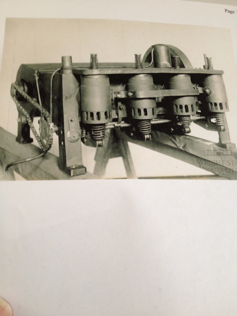
This is one of many photos I managed to obtain that left the engine in its natural metallic finish as opposed to painted black. I opted to take this route to show the detailing. |
| Skyediamonds1985, Image # 34264 | 26 Jun 15 00:22 |
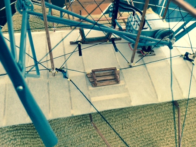
The Wright Bros. had the rigging interconnected such that the wing warping rigging from the pilot's cradle to the wings were also directed to a couple of bellcranks that connected to the rudder. |
| Skyediamonds, Comment for image # 34252 | 26 Jun 15 00:00 |
| In answer to the question about the chains; they were purchased at a local arts & crafts store. These stores sell all kinds of goodies & accessories & of course, chains of all sizes. They ranged designer chains, to tiny chains you barely see that they could pass for tying twine, to chains that are made from brass, copper, & steel. Because there is so much confusion as to what constitutes the original Wright Flyer, I took this opportunity to express artistic license & used brass chains for a little bit of decorative "bling" to break up the monochromatic whites, blacks & grays. I hope I didn't blow up the forum with all those posts. Would like to hear more. -Sky |
| Skyediamonds1985, Image # 34263 | 25 Jun 15 19:10 |
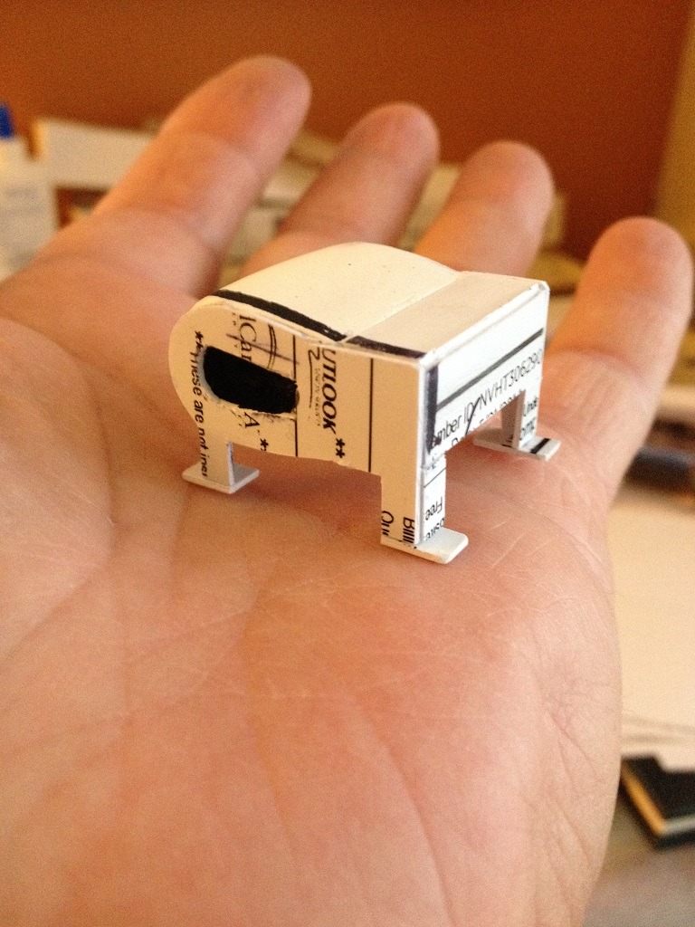
With the legs having the added depth and bottom tie down supports, the Wright engine is starting to really take shape |
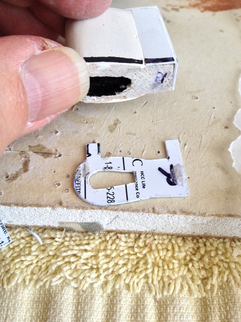
| Skyediamonds1985, Image # 34262 | 25 Jun 15 19:08 |
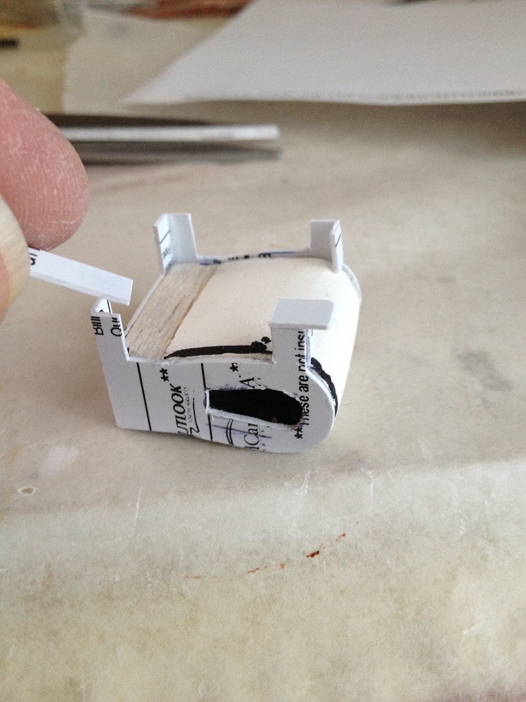
Each leg was given its own "feet." These "feet" are used as supports to tie the engine down to the lower wing |
| Skyediamonds1985, Image # 34261 | 25 Jun 15 19:03 |
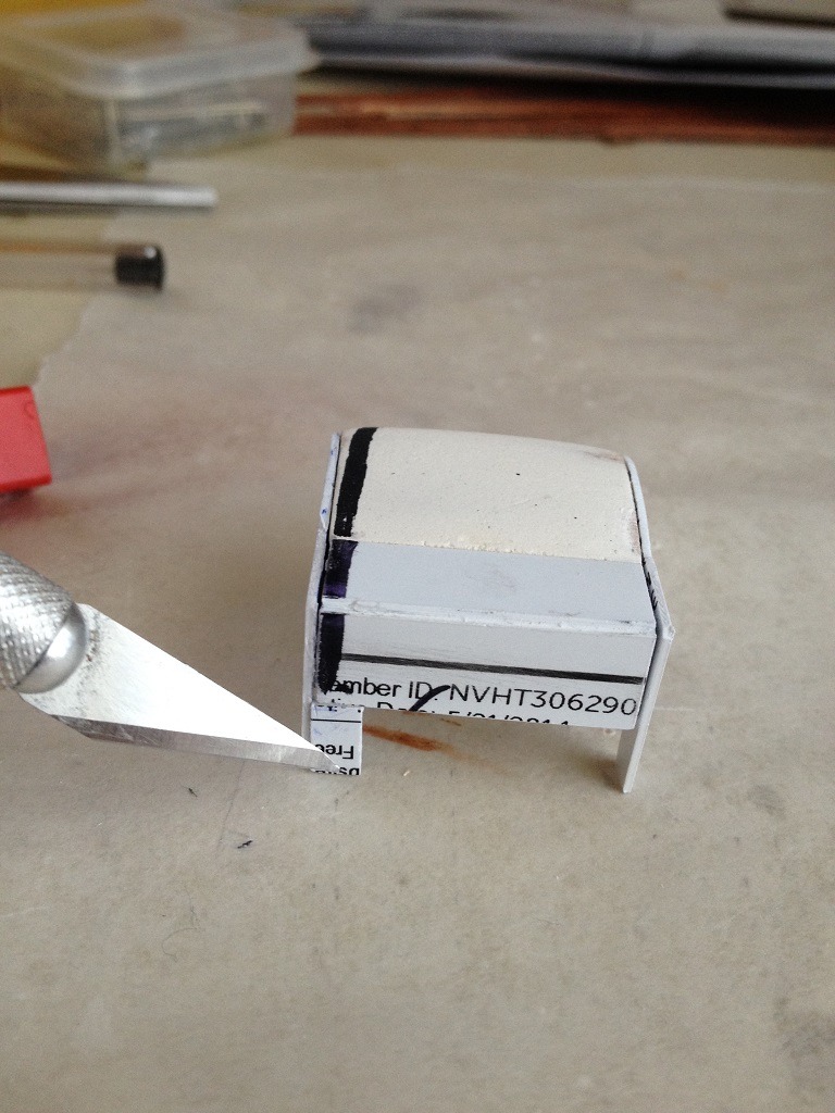
Each leg to the engine was given some added depth |
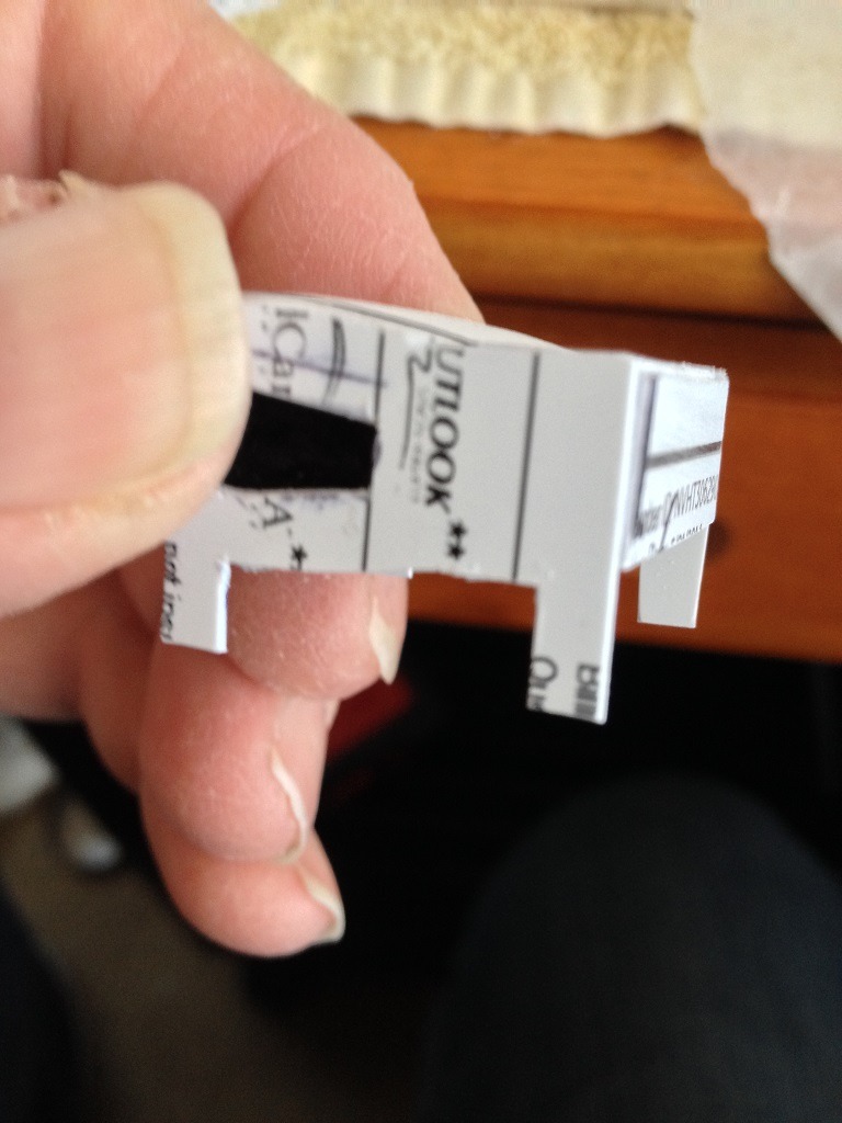
| Skyediamonds1985, Image # 34260 | 25 Jun 15 19:01 |
To help give the legs some added dimension, additional small pieces of plastic card were cut to size of each leg |
| Skyediamonds1985, Image # 34259 | 25 Jun 15 18:58 |
The two plastic sides were then super glued to the sides of the engine block. We can see how the Wright engine is taking shape |
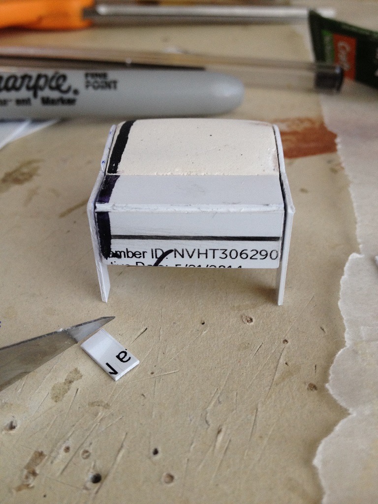
| Skyediamonds1985, Image # 34258 | 25 Jun 15 18:56 |
After cutting the two plastic sides, I hollowed out the side of the engine block for the gears and used a black marking pen to darken the interior |
| Build Thread, Page :
1 2 [ 3 ] 4 (70 posts, 20 posts per page, 4 pages in total)
|
[ < Prev ] [ Next > ] |
