| Build Thread, Page :
1 2 3 4 [ 5 ] 6 7 8 (145 posts, 20 posts per page, 8 pages in total)
|
[ < Prev ] [ Next > ] |
| Creosotewind, Comment for image # 16322 | 08 Feb 10 09:37 |
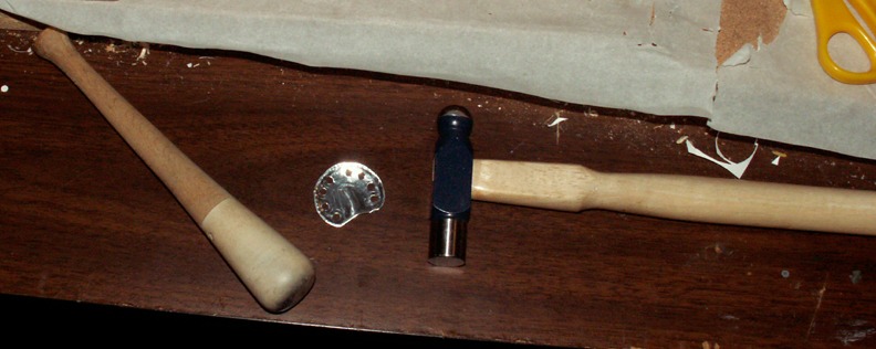
| The pestle (or is that the mortar?) and the jeweler's hammer help to roll the aluminum. The round end of the hammer smooths out some of the overlap. |
| Creosotewind, Image # 16328 | 08 Feb 10 09:29 |
The small box on the side of the frame is the electrical junction box. I added some paper and wood strips to make it look a bit more like the real thing. A simple fix, but seems effective. |
| Creosotewind, Image # 16327 | 08 Feb 10 09:27 |
|
| Creosotewind, Image # 16326 | 08 Feb 10 09:26 |

|
| Creosotewind, Image # 16325 | 08 Feb 10 09:25 |
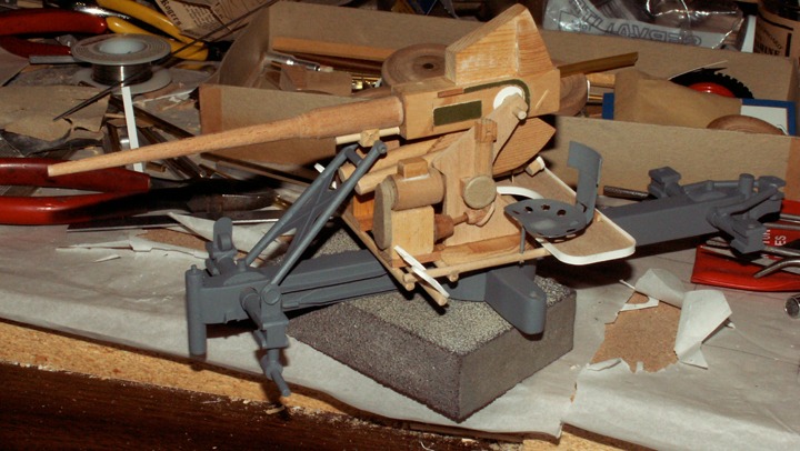
The seats and bottom frame have been primered. |
| Creosotewind, Image # 16324 | 08 Feb 10 09:24 |
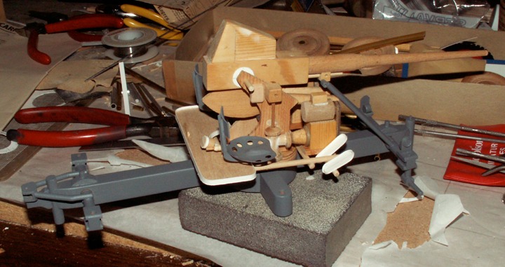
Two down. The seat backs and braces are stiff paper. Attached with white glue and epoxy. |
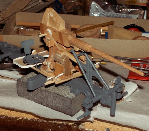
| Creosotewind, Image # 16323 | 08 Feb 10 09:23 |
One down. Can I do another? |
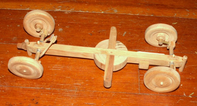
| Creosotewind, Image # 16322 | 08 Feb 10 09:22 |
|
| Creosotewind, Image # 16321 | 08 Feb 10 09:22 |
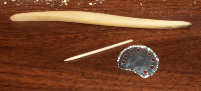
To avoid sharp cut edges, I carefully rolled over the edges upon themselves using the toothpick to define the shape. The other tool helped to roll over the aluminum lip. |
| Creosotewind, Image # 16320 | 08 Feb 10 09:20 |
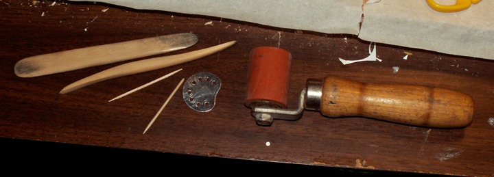
Some of the tools I use for tooling. The small pieces are toothpicks with rounded ends. The bigger pieces are used for clay artists. The brayer is good to roll the material flat. I found that at a yard sale. |
| Creosotewind, Image # 16319 | 08 Feb 10 09:18 |
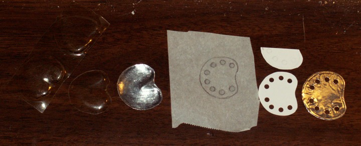
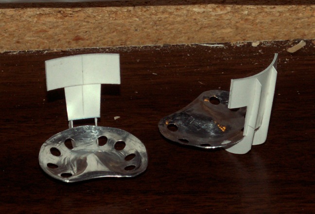
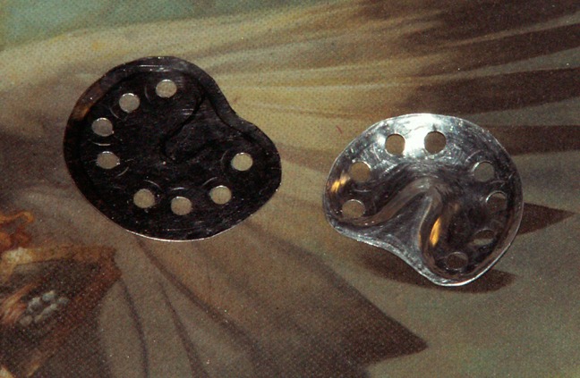
The seats are basically tractor seats. The kit supplies pressed plastic pieces that are not really well defined. I tried my hand at making one in aluminum. The tracing shows the pattern drawing, white showed the stencil pattern and finally on the right is a cut piece of aluminum ready to be shaped. The holes are 1/8", punched from a craft store hole punch. |
| Creosotewind, Image # 16318 | 08 Feb 10 09:15 |
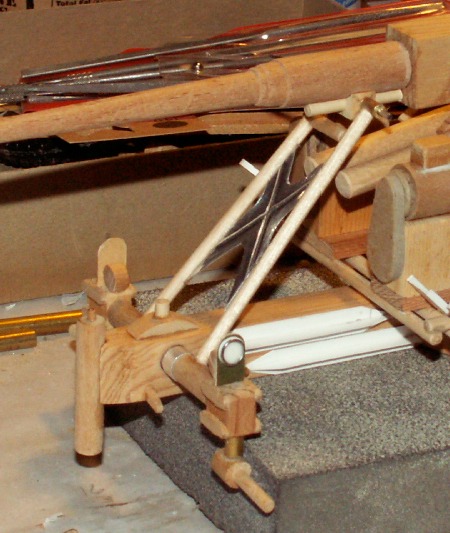
This still shows the brass tubing. I removed those pieces because the adhesive didn't have good shear strength. I replaced the brass with 1/8" wood dowells that were drilled through. |
| Creosotewind, Image # 16317 | 08 Feb 10 09:13 |
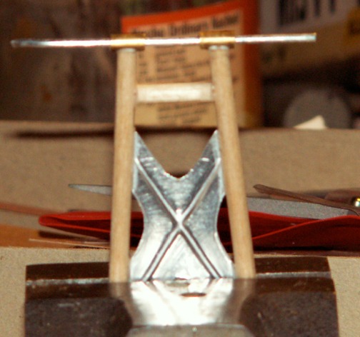
The brace pins to the barrel. I tried glueing brass tubing to the wood, but couldn't get it to stick. |
| Creosotewind, Image # 16316 | 08 Feb 10 09:10 |
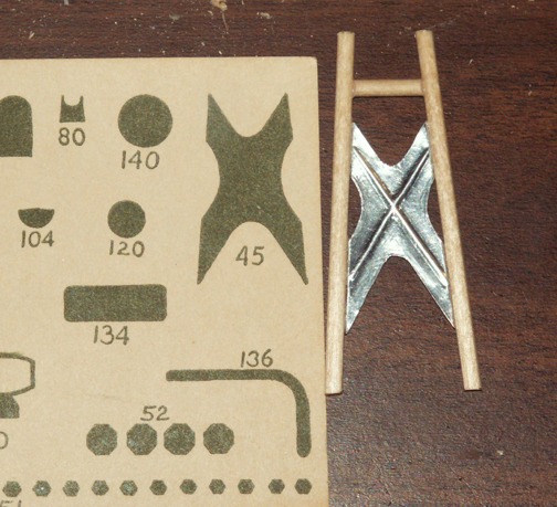
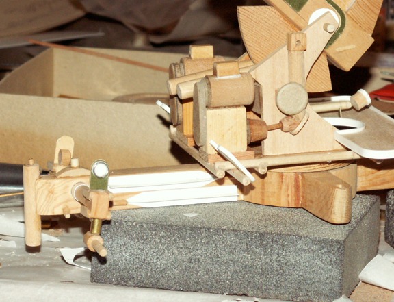
When the gun is in transport, this brace holds the barrel in place. The green piece comes from the kit. More stiff manila paper. The real piece has the stiffeners embossed in the metal. I did the same thing with some tooling aluminum and a toothpick. |
| Creosotewind, Image # 16315 | 08 Feb 10 09:08 |
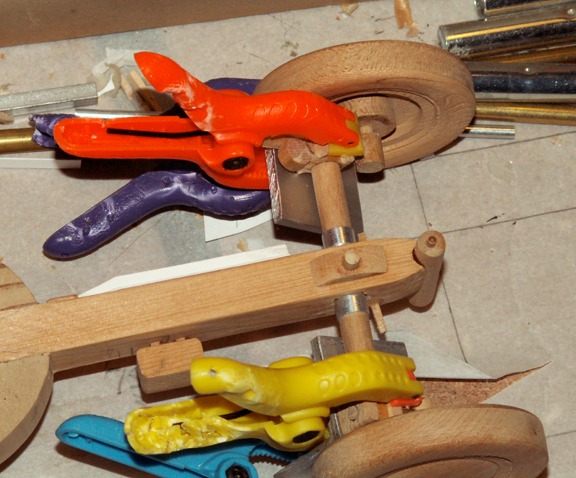
Glueing the rear wheel spindles. Aluminum angle is used to keep them square. The bite marks on the clamps are from my son's dog. The axle is kept in place with the two pieces of aluminum tube slipped over the axle dowell. |
| pfinn, Comment for image # 16313 | 08 Feb 10 09:08 |
| This is very cool! Thanks for sharing this. Phil |
| Creosotewind, Image # 16314 | 08 Feb 10 09:06 |
The rear axles include brake lights and these reflectors. The green shape came with the kit. Stiff manila paper. I added the bezel (wrapped solder) and the white disk (hole punch) to later be painted as reflectors. |
| Creosotewind, Image # 16313 | 08 Feb 10 09:04 |
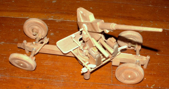
Wheels up. Almost ready to transport. |
| Creosotewind, Image # 16312 | 08 Feb 10 09:03 |
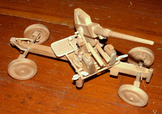
Wheels down..... |
| Creosotewind, Image # 16311 | 08 Feb 10 09:02 |
Showing how the front and rear wheels drop. The vertical posts at either end, and two on the outriggers (not shown) have pads that crank down on the real gun to act as stabilizers. |
| Build Thread, Page :
1 2 3 4 [ 5 ] 6 7 8 (145 posts, 20 posts per page, 8 pages in total)
|
[ < Prev ] [ Next > ] |
