| Build Thread, Page :
1 2 [ 3 ] 4 5 (94 posts, 20 posts per page, 5 pages in total)
|
[ < Prev ] [ Next > ] |
| simpleflyer, Image # 19209 | 10 Sep 10 16:50 |
|
| simpleflyer, Image # 19208 | 10 Sep 10 16:49 |
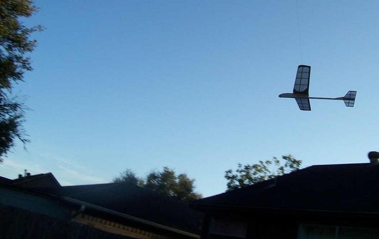
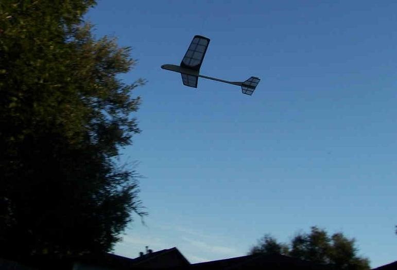
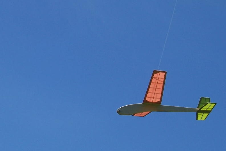
By late afternoon, the Jr. CloudBuster was ready for flight. A couple of test glides without the swing line showed no bad flight habits. Attached the swing line and did some test flights which went well. |
| simpleflyer, Image # 19206 | 10 Sep 10 10:06 |
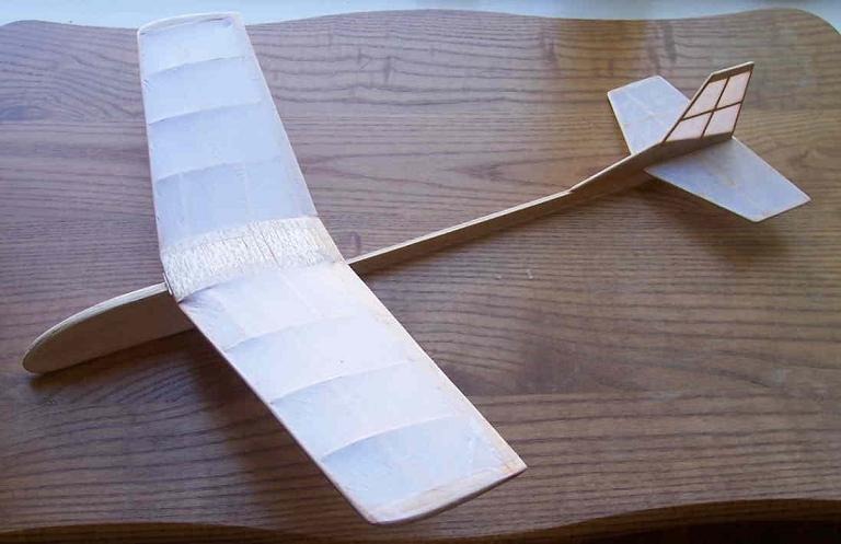
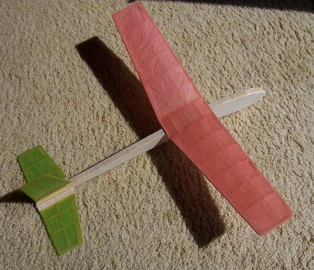
Covered with some leftover white wrapping tissue and a couple coats of thinned white glue. A couple more coats, a nut and bolt in the nose for balance, a bit of string attached to the wing, and we're ready to go to the backyard for some test flights :o) |
| FLYBOYZ, Comment for image # 19198 | 09 Sep 10 14:15 |
| This babby is going to really fly good! |
| simpleflyer, Image # 19198 | 09 Sep 10 12:51 |
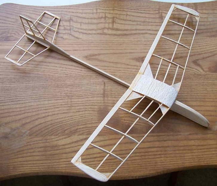
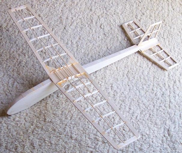
The frame complete and ready for covering. |
| simpleflyer, Image # 19197 | 09 Sep 10 12:48 |
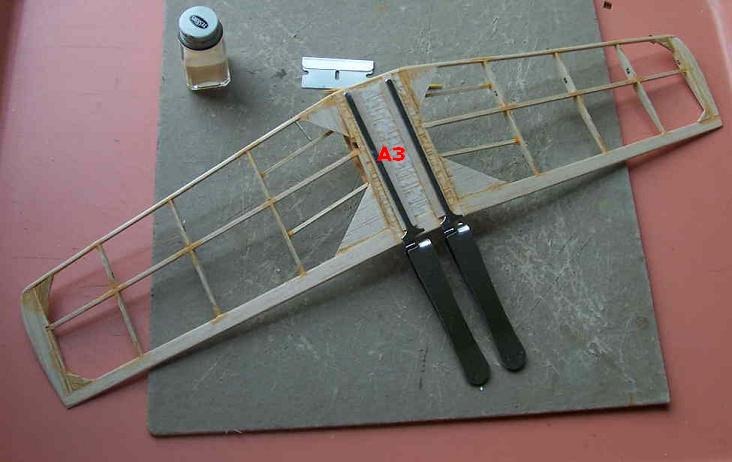
The retaining stripA3 are glued in place. A while back we found a foot square piece of !/64 plywood at the LHS. We're cutting it into small strips and using it for retaining strips. We will see how it compares to the 1/32 balsa in strength. |
| simpleflyer, Image # 19196 | 09 Sep 10 12:47 |
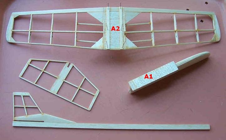
The Jr. Cloudbuster is quickly coming together. Wing platform A1 and spacing strips A2 are glued in place. |
| simpleflyer, Image # 19189 | 08 Sep 10 19:04 |
Wing dihedral formed. !/32 sheet glued to bottom of the pod forming the tail boom slot. Vertical tail attached to tailboom. |
| simpleflyer, Image # 19188 | 08 Sep 10 19:02 |
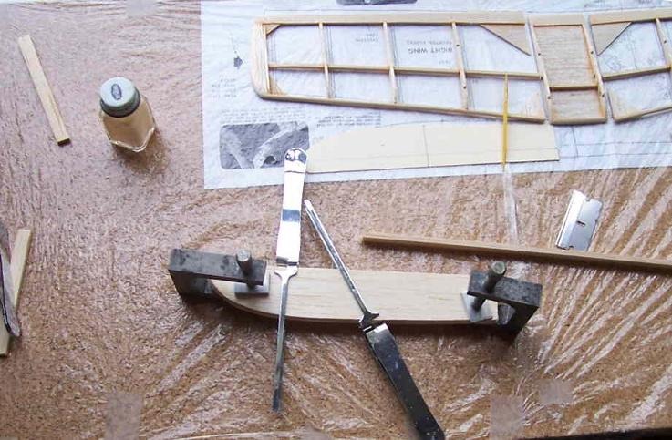
The nose pod parts glued together. |
| simpleflyer, Comment for image # 19187 | 08 Sep 10 19:00 |
| 0ooops, should have posted--The fuselage pod is made of 1/8 sheet with 2 1/16 sheet doublers. The area removed from the 1/8 sheet part will become a slot for the tail boom. |
| simpleflyer, Image # 19187 | 08 Sep 10 18:57 |
The fuselage pod is made of 1/8 sheet with 2 1/16 sheet doublers. The area removed from |
| pfinn, Comment for image # 19160 | 07 Sep 10 18:48 |
| Super! |
| simpleflyer, Image # 19164 | 07 Sep 10 15:57 |
The flight pic shows the prominent drooping nose, so we call it the 'Droop Snoot' :o) |
| simpleflyer, Image # 19163 | 07 Sep 10 15:55 |
It was built early this summer when it was getting hot and the colors were chosen to remind us that 'pumpkin season' and cooler days will eventually come;o) |
| simpleflyer, Image # 19162 | 07 Sep 10 15:53 |
If anyone is interested what the model was that was used in illustrating the sliding wing mount. It is a scratchbuilt using the wing and tail shapes of the Zaic Falcon and an original built up profile fuslelage. |
| simpleflyer, Image # 19161 | 07 Sep 10 15:35 |
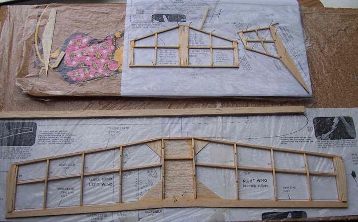
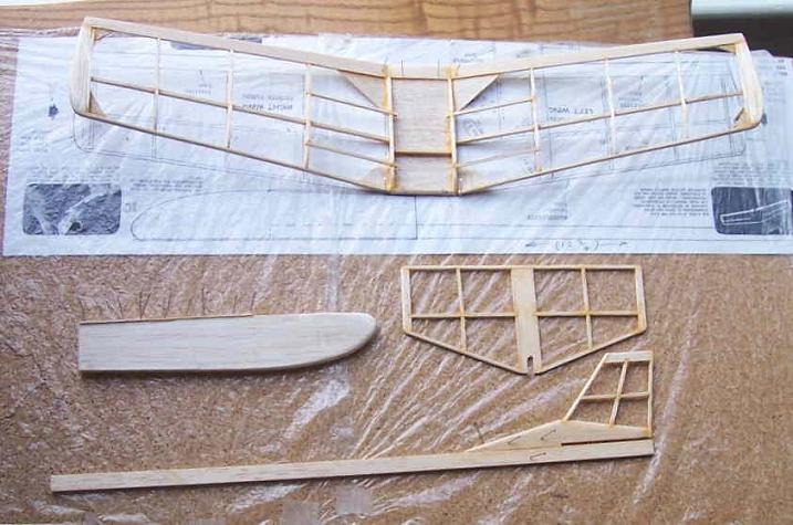
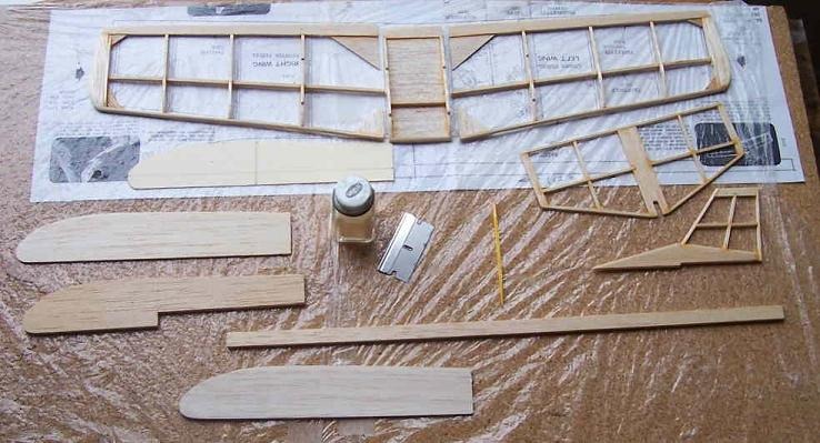
Since the Cloud Buster fleet is beginning to show its age, a new one is in order. Having a duplicate CB kit, we took the wing parts and built a new wing. We shortened it by two inner bays and added a reinforced center section. This reduced the wing area about 84 percent so we adjusted the tail parts by this amount. The wingspan of this version will be 14 inches. Here are the new wing and tail parts. |
| simpleflyer, Comment for image # 19160 | 07 Sep 10 15:30 |
| Thanks, Phil, for your comments. To date, I have not had any major wing breaks in the outer portions of the wing when using the sliding wing mount and the 'heavy duty' wing center section. This was one of the primary reasons for going to removeable wings on the swing control models. In addition to the portability of the model, we discovered that by making the mounting system so that the wing was moveable it sustained less damage in collisions. The sliding wing mount is designed so that the wing is free to move forwards as well as backwards. So far, in nearly all of our collisions we get either one of two conditions. (1) The model hits nose first and the fuselage tends to stop abruptly and the wing moves forward before breaking. (2) The outer wing hits first and stops and the fuselage tends to slide forward. Usually the damage to the wing in either condition is in the outer portions and is relatively small. |
| pfinn, Comment for image # 19160 | 06 Sep 10 15:58 |
| Nice. Do you think that having this pretty much indestructable wing attachment may lead to breaks further out along the wing? But still, excellent idea and excecution. By the way, the strongest gussets have the grain running along the edge opposite the joint being reinforced (in this case the hypotenuse). |
| simpleflyer, Image # 19160 | 06 Sep 10 13:58 |
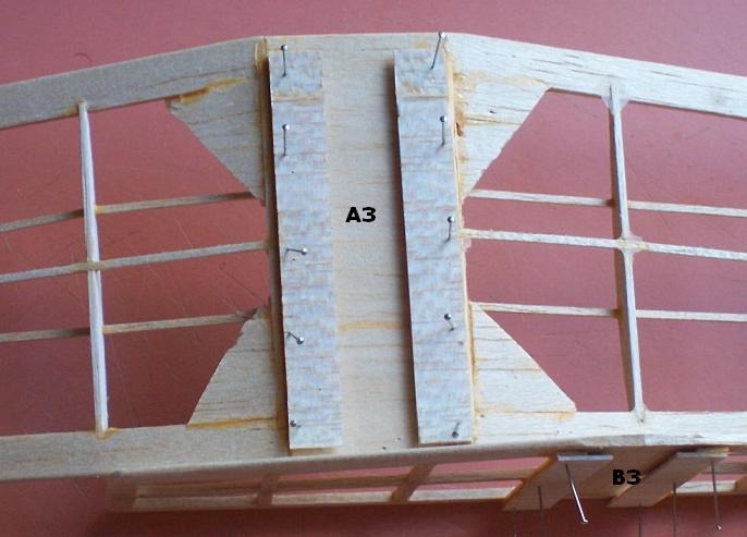
A closeup of the opposing throughts at 'A3' formed by the overlapping strips in the previous picture. 'B3' shows an edge view. The platforms on the fuselage slide through these spaces. |
| simpleflyer, Image # 19159 | 06 Sep 10 13:56 |
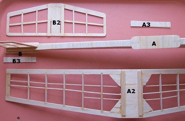
How the mounting system works. 'A' is the wing mounting platform on the fuselage. 'A2' is the wing surface that will rest on the platform 'A'. Two balsa strips the thickness of the platform are glued on both sides of 'A2' spaced the width of 'A'. 'A3' are strips slightly wider and are glued on top of the strips at 'A2', with the overlap towards the center of the wing. |
| Build Thread, Page :
1 2 [ 3 ] 4 5 (94 posts, 20 posts per page, 5 pages in total)
|
[ < Prev ] [ Next > ] |
