| Build Thread, Page :
<< 12 13 14 15 16 [ 17 ] 18 (348 posts, 20 posts per page, 18 pages in total)
|
[ < Prev ] [ Next > ] |
| biplane guy, Comment for image # 35875 | 15 Apr 16 20:05 |
| Just read about your S.E. 5, would love to see pics. I grew up fascinated by biplanes, never was a jet fan. My last build before the kids came along was a Liberty Sport Sig kit. Last summer my daughter bought the two of us a ride in a WACO UPF-7. Thrill of a lifetime. Wish I could find a kit. |
| biplane guy, Comment for image # 35875 | 15 Apr 16 19:58 |
|
| biplane guy, Comment for image # 35875 | 15 Apr 16 19:58 |
| Hi Sky, I appreciate the welcome. Sounds like we're in the same boat (or plane). I'm just getting back into building after a 40 year hiatus for all of the same reasons. I will take you up on the offer to share details about your build. Thanks again, Keith.
|
| Skyediamonds1985, Comment for image # 35875 | 15 Apr 16 19:54 |
| I noticed you added the extra cooling fins on each cylinder for the exhaust manifolds. Excellent work of detailing!! I'm currently working on my S.E. 5. |
| Skyediamonds1985, Comment for image # 35875 | 15 Apr 16 19:48 |
| Welcome to the VA, if you're a new member. Thank you for the compliments on my PT-17 build. It was my first detailed build in over 30 years. Had to take time out to raise a family, work, and so on. I really enjoyed viewing your builds and postings. I felt like I was rebuilding the PT-17/N2S all over again. Still have the model and several details if interested. -Sky |
| biplane guy, Comment for image # 35870 | 15 Apr 16 10:53 |
| Dash was cut from metal stock using gauge pics from a PT-17 found online that were mounted in a similar configuration to the particular aircraft being simulated. They were scaled to size by my computer savvy wife, printed on glossy photo paper, and then carefully cut out and glued in place after touching-up the cut paper edges with a black marker. |
| Creosotewind, Comment for image # 35869 | 15 Apr 16 10:50 |
| All this looks really sharp. |
| biplane guy, Comment for image # 35875 | 15 Apr 16 10:43 |
| Prop shaft detail, exhaust detail, spark plugs and wiring detail. Spark plug wires cut from 24 gauge jewelry wire. Tubes connecting cylinder heads cut from scrap 1/16 wire rod from kit. |
| biplane guy, Image # 35875 | 15 Apr 16 10:36 |
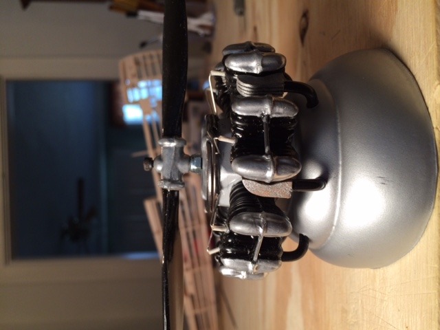
Engine side view |
| biplane guy, Comment for image # 35872 | 15 Apr 16 10:31 |
| Placement of the cable housings and brass tubes for the rudder pedals is critical since the cardboard cockpit must have room to seat down against the side keel (A6/A7) with the brass tubes protruding through the printed rudder pedals. See cockpit detail. |
| biplane guy, Comment for image # 35872 | 15 Apr 16 10:26 |
|
| biplane guy, Comment for image # 35872 | 15 Apr 16 10:25 |
| Cable housings exit fuselage on either side of the tailwheel support. Cables attach to the rudder control horns and to the rudder pedals which pass through the small brass tubes. (Final connection pictures to follow). The brass tube epoxied into the end of the upper ball joint is for the metal pushrod to the elevator horn which will be cut to size and epoxied into the brass tube. |
| Don C, Comment for image # 35864 | 15 Apr 16 10:23 |
| Very nice work! I gave up connecting the controls on mine because I couldn't figure out the stick. Sure wish you had done this a couple of years ago. |
| biplane guy, Image # 35872 | 15 Apr 16 10:16 |
Rudder control cables |
| biplane guy, Comment for image # 35864 | 15 Apr 16 10:12 |
| Note added plywood for control horns on ailerons and elevator and balsa for the rudder control horns (one for each rudder pedal). |
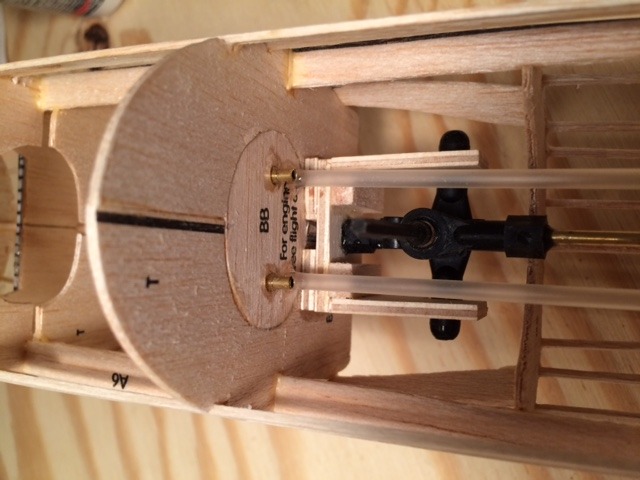
| biplane guy, Image # 35871 | 15 Apr 16 09:58 |
Bottom view of stick assembly |
| biplane guy, Comment for image # 35869 | 15 Apr 16 09:52 |
| Prop is attached with a hex screw secured to a blind nut epoxied to the back of the small vinyl disk that was originally part of the rubber band motor assembly. A nut with plastic insert is tightened against the disc to secure the prop shaft (screw) while allowing the prop to rotate freely. Spark plugs are made from short pieces of plastic insulation stripped from #18 thermostat wire. A 1-1/4" dia. key ring simulates the conduit for the spark-plug wiring. Exhaust headers were carved from 1/4" square balsa stock and the fins were cut with a razor saw. |
| biplane guy, Comment for image # 35866 | 15 Apr 16 09:34 |
|
| biplane guy, Comment for image # 35866 | 15 Apr 16 09:33 |
| Cable-type pushrods allow flexible connections from the control stick to the aileron bellcranks. Holes in the wing ribs were made with a leather punch. Crimp eyes allow the cable ends to be screwed to the stick ball joint. |
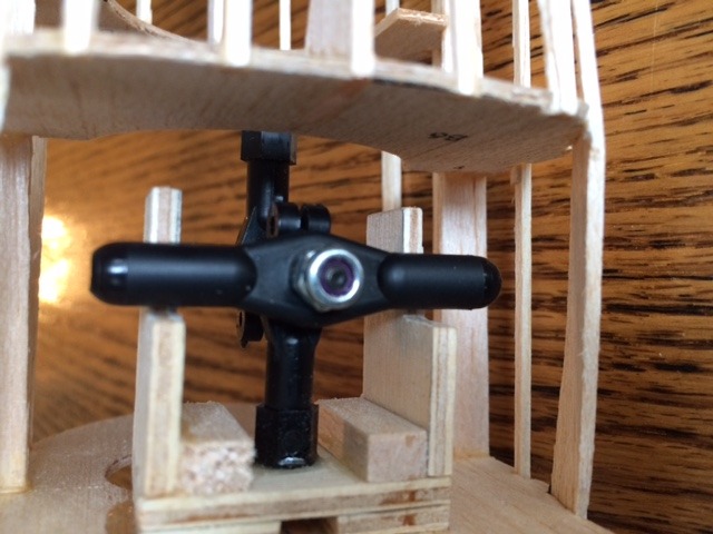
| biplane guy, Comment for image # 35865 | 15 Apr 16 09:25 |
| The control stick is fabricated from three ball joints: the middle one is screwed and epoxied to a plywood platform attached to former B5, the upper one at the top for the elevator pushrod. The lower ball joint attaches to the two aileron pushrods. The ball joints are secured together with a single hex screw into which a cut-off hex wrench is epoxied to become the control stick. |
| Build Thread, Page :
<< 12 13 14 15 16 [ 17 ] 18 (348 posts, 20 posts per page, 18 pages in total)
|
[ < Prev ] [ Next > ] |
