| Build Thread, Page :
<< 12 13 14 15 16 17 18 (348 posts, 20 posts per page, 18 pages in total)
|
[ < Prev ] |
| biplane guy, Image # 35875 | 15 Apr 16 10:36 |
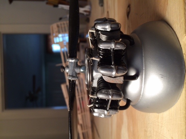
Engine side view |
| biplane guy, Comment for image # 35872 | 15 Apr 16 10:31 |
| Placement of the cable housings and brass tubes for the rudder pedals is critical since the cardboard cockpit must have room to seat down against the side keel (A6/A7) with the brass tubes protruding through the printed rudder pedals. See cockpit detail. |
| biplane guy, Comment for image # 35872 | 15 Apr 16 10:26 |
|
| biplane guy, Comment for image # 35872 | 15 Apr 16 10:25 |
| Cable housings exit fuselage on either side of the tailwheel support. Cables attach to the rudder control horns and to the rudder pedals which pass through the small brass tubes. (Final connection pictures to follow). The brass tube epoxied into the end of the upper ball joint is for the metal pushrod to the elevator horn which will be cut to size and epoxied into the brass tube. |
| Don C, Comment for image # 35864 | 15 Apr 16 10:23 |
| Very nice work! I gave up connecting the controls on mine because I couldn't figure out the stick. Sure wish you had done this a couple of years ago. |
| biplane guy, Image # 35872 | 15 Apr 16 10:16 |
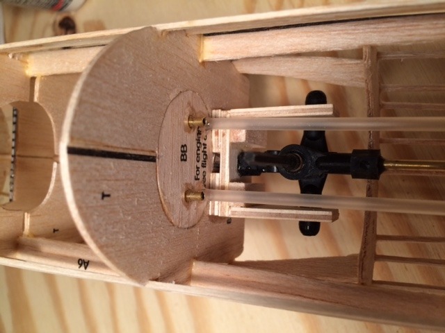
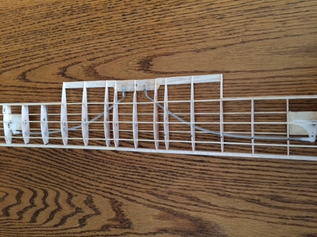
Rudder control cables |
| biplane guy, Comment for image # 35864 | 15 Apr 16 10:12 |
| Note added plywood for control horns on ailerons and elevator and balsa for the rudder control horns (one for each rudder pedal). |
| biplane guy, Image # 35871 | 15 Apr 16 09:58 |
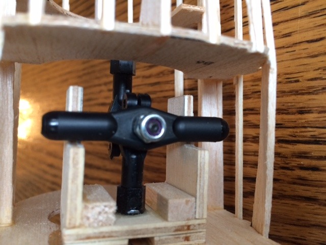
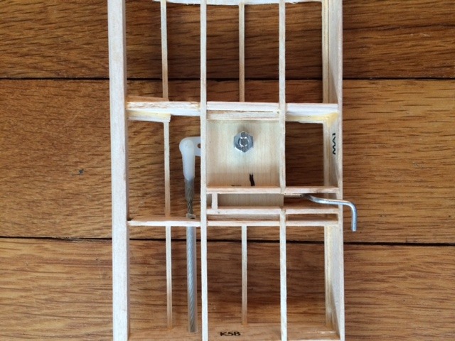
Bottom view of stick assembly |
| biplane guy, Comment for image # 35869 | 15 Apr 16 09:52 |
| Prop is attached with a hex screw secured to a blind nut epoxied to the back of the small vinyl disk that was originally part of the rubber band motor assembly. A nut with plastic insert is tightened against the disc to secure the prop shaft (screw) while allowing the prop to rotate freely. Spark plugs are made from short pieces of plastic insulation stripped from #18 thermostat wire. A 1-1/4" dia. key ring simulates the conduit for the spark-plug wiring. Exhaust headers were carved from 1/4" square balsa stock and the fins were cut with a razor saw. |
| biplane guy, Comment for image # 35866 | 15 Apr 16 09:34 |
|
| biplane guy, Comment for image # 35866 | 15 Apr 16 09:33 |
| Cable-type pushrods allow flexible connections from the control stick to the aileron bellcranks. Holes in the wing ribs were made with a leather punch. Crimp eyes allow the cable ends to be screwed to the stick ball joint. |
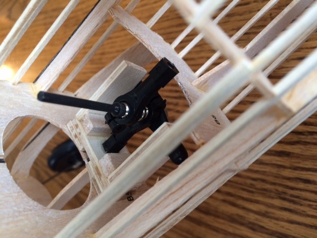
| biplane guy, Comment for image # 35865 | 15 Apr 16 09:25 |
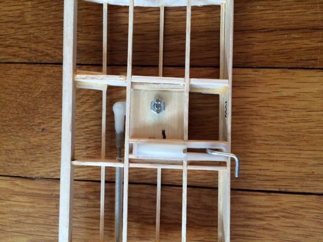
| The control stick is fabricated from three ball joints: the middle one is screwed and epoxied to a plywood platform attached to former B5, the upper one at the top for the elevator pushrod. The lower ball joint attaches to the two aileron pushrods. The ball joints are secured together with a single hex screw into which a cut-off hex wrench is epoxied to become the control stick. |
| biplane guy, Comment for image # 35870 | 15 Apr 16 09:11 |
| Kit is being built to replicate the Navy version of the PT-17 on display at the Carolinas Aviation Museum in Charlotte, NC. The brass tubes at the rudder pedals are for the push rods that will operate the rudder. |
| biplane guy, Image # 35870 | 15 Apr 16 09:06 |
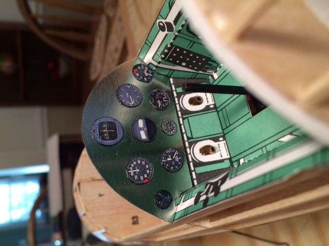
Cockpit mods |
| biplane guy, Image # 35869 | 15 Apr 16 08:59 |
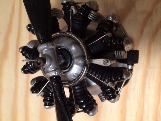
Engine detail |
| biplane guy, Image # 35868 | 15 Apr 16 08:53 |
Push rod exit detail |
| biplane guy, Image # 35867 | 15 Apr 16 08:52 |
Aileron control mods |
| biplane guy, Image # 35866 | 15 Apr 16 08:45 |
Aileron controls to stick |
| biplane guy, Image # 35865 | 15 Apr 16 08:43 |
control stick |
| biplane guy, Image # 35864 | 15 Apr 16 08:33 |
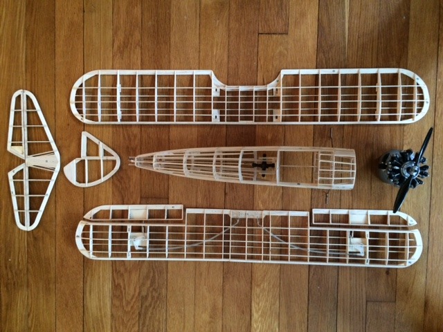
Ready to cover |
| Build Thread, Page :
<< 12 13 14 15 16 17 18 (348 posts, 20 posts per page, 18 pages in total)
|
[ < Prev ] |
